I'm working on a project (which I'm calling TCBus) that uses a CAN bus.
I want to control the bus with a Windows app. USB is a typical way to interface
peripherals to Windows, so I decided to make a USB to CAN translator.
For the USB part of it, I've experimented with the FT245R, which is a
decent device, but I was kinda wanting to have a "one chip solution", with the USB and custom controller code in the same device.
So I looked into Microchip's "FSUSB" USB demo board and decided to use their solution.
After fiddling with the FSUSB (and porting their demo app to C++), I created my first version of a USB-to-CAN device:
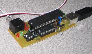
This version was a testbed and had the attendant buttons, jumpers, and socketed ICs.
I had previously developed a standalone CAN bus to learn CAN and the MCP2515, so for
the CAN portion of this device I simply ported my VC++ code to Microchip C... not too onerous.
I then redesigned my hardware to fit into a project box:
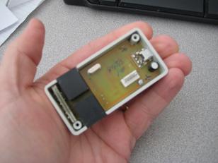
(I'm using RJ45's for the CAN bus... DB9's are bulky and expensive)
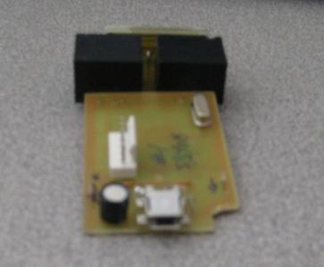
Here's the foil side; I've taken to using SMT parts for both size and ease of assembly:
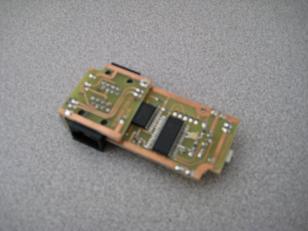
In order to use only single-sided PCBs (2 sided is hard for a hobbyist to do accurately) and fit it all into a 1" x 2.5" box, I made a few small daughterboards.
On one end is the CAN transceiver (hidden between the end PCB and RJ45 jacks) and an activity monitoring 2-color LED driven by a PIC12F508 (which does buffering and one-shot).
The LED aligns with a small hole in the box and shows green on CAN-tx and red on CAN-rx:
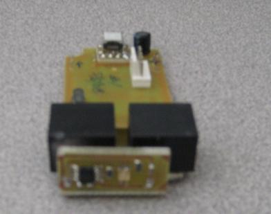
On the other end is a mini-USB connector.
I needed this daughterboard to raise the connector to the center of the box (connectors are supposed to be centered, right? :)
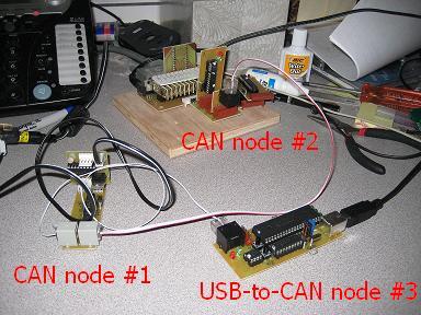
Here's my test rig with 3 CAN nodes (the USB xlator is a node):
* Node #1 is just a PIC-based node on the bus that echos when addressed.
* Node #2 is driven by PC software via my parallel port interface tool, and is in passive "listen" mode, acting as a packet sniffer.
* Node #3 is the CAN-to-USB translator ("testbed" version shown here.. I put it in a box only after I had proven the h/w and f/w).
The amazing thing is that it all works really well!
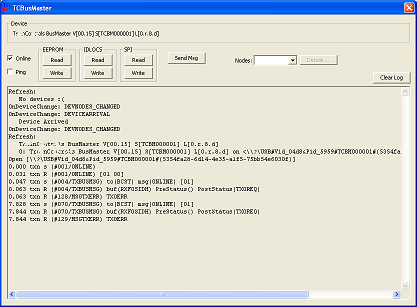
I wrote a testapp that does the Windows side of USB, talks to the device, and talks to other nodes across the CAN bus.
The whole thing is "plug and play" - when CAN nodes are added or removed from the physical bus the testapp detects that and updates the configuration automatically.
Here's a movie of the first time the bus worked!
Questions? Comments? email me!