Several concepts and technical terms are critical to a discussion of covered bridge design and construction. A truss is a triangular system of timbers designed so that each member helps to support the others; together they support the weight of the structure over a span. One of the earliest bridge truss designs was the king post truss, formed by one vertical member (or post) in the center with two diagonals and a bottom chord (horizontal member). The next development was the queen post truss (or modified king post), in which the peak of the kingpost triangle was replaced by a horizontal crosspiece, or upper chord, allowing the truss to span a greater length. An important development in bridge design was the invention in 1820 by Ithiel Town of the lattice truss, consisting of a series of overlapping triangles that resembles a garden lattice. The advantage of the Town lattice design is that it can be used to support spans well over a hundred feet in length. Due to its versatility, the Town lattice truss became the most popular covered bridge design in Georgia. (Covered Bridges of the South, Allen: 1970).
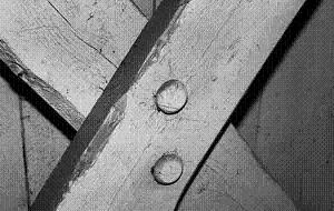
The members of wooden bridges are generally held together by wooden pegs, or trunnels (from "tree nails"). The wooden members of the bridge were often cut off-site, including boring of the holes for trunnels, and assembled in place. Builders used a numbering system to allow easy onsite assembly of the bridge pieces in a "pre-fab" fashion; the numbers are still visible on lattice members in many bridges.
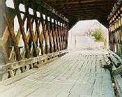
Other elements of covered bridge design include piers that support the bridge over the stream bed. Large wooden heel plates installed longitudinally under the chords distribute the downward load of the trusses as they cross the sole plates, lateral members that rest on the tops of the piers. Abutments provide support to the bridge at the stream bank and sometimes act as retaining walls. Approaches are the sections of the bridge that span from the abutment to the pier; they are sometimes incorporated into the covered portion of the bridge. A system of floor beams and joists between the chords support the planks of the floor decking;cross-braces between the floor beams provide additional stability. Longitudinal treads are often installed over the decking to provide a smooth surface for the wheels of vehicles. Chin braces provide lateral support and are typically located over the piers at each end of the bridge, where unfortunately, they are susceptible to damage by vehicles. The bridge entrances, or portals,sometimes project outward over the approaches to provide additional protection of the interior of the bridge from the elements.
Bridge roofs were originally constructed of wood shingles; many have been replaced by metal roofs. A system of ceiling beams, rafters, and cross-braces support the roof; additional stability is sometimes provided by diagonal knee braces.