April 13, 2007
I need an inexpensive (USB-based) logic analyzer.
I found:
- Something called the HobbyLab for $170 (the high end of my price range), and I found someone who had bought one. I emailed him, and his review wasn't overly positive (seems to be a Russian-made clone of another scope), so I skipped it.
- The BitScope, which is very powerful but $345 is way more than I wanted to spend.
- The USBee, but that's $545 :(
I then found the Parallax BASIC Stamp Logic Analyzer (BSLA) for only $79 - more in my price range. It's based on the USBee and is intended for integrated monitoring of BASIC Stamp modules (it has the Stamp's standard 24-pin DIP form factor), but I figured that I could make a simple PC board that would adapt it to my setup, so ordered one (UPS express!).
It's a deceptively simple device, utilizing a CY7C68013 USB Microcontroller sandwiched between a male and a female socket in the form factor of the Parallax BASIC Stamp modules (24 pin .600" DIP). It's intended to be placed between a Stamp and a Stamp-controlled board,
but I figured that if I made a simple adapter I could use it to capture just about anything. It has a 2Msps rate, which is fine for my applications. I was pleased to find that it comes with a 6' USB-A to mini-USB cable.
Here's what it looks like:
The controlling app (for Windows, created by the USBee folks) is a free download, and has a decent control set. Most notable is that it has many triggering options,
has built-in SPI and I2C decoding (I'm using SPI), and can capture 2 minutes (!) worth of samples (because my PC has 1GB of RAM).
The module has 16 TTL-level-detecting inputs (P0 thru P15) plus 4 additional inputs: SIN, SOUT, RES, and Vdd. On a Stamp module, SIN and SOUT are the serial interface pins, RES is the reset line, and Vdd is the 5V power downstream from the Stamp's onboard 5V regulator. But on the BSLA they're just four more TTL level sensors, so for my stand-alone usage there are 20 logic lines (incl. 4 with "funny names").
Note: Experimentation shows that the SIN and SOUT pins might be looking for RS232 voltages, not TTL voltages as Parallax support initially indicated - I'm awaiting clarification from Parallax. If these are indeed looking tor RS232 levels then I'll have to cobble together a level translator :(, maybe using a MAX232 [Datasheet (PDF)].
Here's the standard pinout of the Stamp module; the pins in green are those monitored by the BSLA:
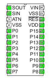
The BSLA gets its power from the USB port, and all 20 inputs appear to have very weak pull-ups. When the BSLA s/w is run with nothing connected to the pins, the inputs all register high.
The two VSS pins are, of course, ground, and they're tied to the USB ground. VIN (used to supply >5V to the Stamp's regulator) doesn't appear to be connected on the BSLA. ATN (which on a Stamp is connected to the PC's serial port's DTR) also appears to be unconnected on the BSLA.
The project that I initially developed this for was based on a PIC16F57 in a 28-SDIP (.300") package. The BSLA is a 24-DIP .600 format, so I designed/etched a couple of PCBs and made an adapter:

The 'F57 is perched on the top (ZIF socket coming soon...), the BSLA in the middle, and 28-SDIP pins on the bottom (for plugging this thing into a board that uses an 'F57). All pins are carried from the bottom to the 'F57 on the top, and the lower PCB does some circuit routing in order to connect all 20 of the 'F57's I/O lines to the BSLA's inputs. It would have been a simpler design if I put the BSLA above the 'F57, but I need to be able to remove the 'F57 for programming, so it really needed to be on top.
In the above pic, notice the gold pins with loops at the top:

Because of the relatively tall height of the BSLA, I needed some longer pins for connecting the two PCBs, and I found those at a local jewelry shop. I'm thinking the rings might come in handy for attaching test clips.
Here's the 'F57 plus BSLA inserted into my project board:

This is a USB to CAN translator: the small chip on the right is an FT245R [Datasheet (PDF)] and the chip on the left behind the xtal is an MCP2515 [Datasheet (PDF)]). The 'F57 manages data exchange between the two.
And here it is all connected and running:

The black cable connects to the BSLA, the gray cable connects to my board (and both connect to the same PC). The green LED is on, indicating that my custom Windows app and the 'F57 are talking!
Here's a screenshot of the BSLA app capturing a communication cycle:

The larger image (click on the pic) shows that the BSLA easily captures a 1us (0.000001 second) wide pulse.
Notice that the BSLA isn't showing it's usual UI.
I hacked the BSLA app to display a PIC16F57 and my device's signal names :)
More info on my BSLAHack project, including a downloadable app and source, can be found here.
Someday I might build an optoisolated interface for the BSLA (not needed for the above project), but for now this Frankenstein adapter works great!.
One year later...


